")
")

A suitable circular absorbing or phase grating is called Fresnel zone plate (FZP) [Fre 1866]. A FZP focuses the incoming beam to a point focus (fig. 1). The minimum diameter of the focus reached is 15 nm for X-rays in 2008. There are also zone plates reflecting the incoming light.
These types of Fresnel zone plates can be distinguished:
| Reflecting Fresnel zone plates | Condenser zone plates |

Fig. 1: Focusing X-rays with a diffracting zone plate
As for visible light, Fresnel zone plates for X-rays can be absorbing or phase shifting. Absorbing zone plates are more common in the X-ray range. They are made of an X-ray absorbing material, e. g. some micrometers gold, on a membrane transparent for X-rays, e. g. Si3N4. Normally the absorber metal is structured by electro deposition into a pre-structured resist. The resist is structured by electron or ion beam writing.
Table 1 gives an overview over the principal parameters achieved with Fresnel zone plates in 2009.
| Parameter | symbol |
Typical values |
|
| micro zone plate | condenser zone plate |
||
| Diameter | D | <0.1 mm | <10 mm |
| Focal length | f | 0.5-1.5 mm | <20 mm |
| Number of zones | N | 100-1000 | <50.000 |
| Minimum zone width |  |
15-50 nm | 30-50 nm |
| Spatial resolution (Rayleigh criterion) |  |
1.22 nm |
|
| Diffraction efficiency |  |
(5...30)% | |
Table 1: Typical parameters of transmission X-ray Fresnel zone plates [VDI 2009c]
As it is technically demanding to produce the narrow outer rings of a zone plate, sometimes so called "composite zone plates" are used. These consist of an inner zone plate used in 1st diffraction order surrounded by an outer zone plate ring with less narrow structures used in 2nd diffraction order (fig. 2). In this way the outermost ring structures of the outer zone plate are less fine and less difficult to produce.
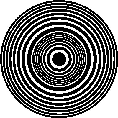
Fig. 2: Composite zone plate with inner zone plate and outer zone plate, used in first respectively second diffraction order
Calculation of Fresnel zone plates
The width of the rings of the circular grating decreases with increasing radius  of the rings. The ring radii can be calculated for monochromatic light of the wavelength
  emitted by a point source Q focused to a point P at a distance of
  with
with  a natural number, g the object distance and b the image distance [Sor 1875]. For each optical path from the source through the zone plate to the focus point, the light should interfere constructively. Fig. 3 shows the optical path for light hitting the zone plate at a distance from the optical axis.
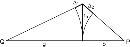
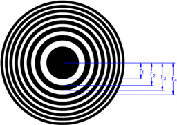
Fig. 3: Sketch of the optical path difference between the source point Q and the focus point P at a distance from the optical axis
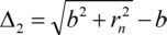
The optical path differences are
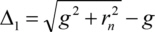
and
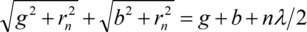
When the total optical path difference is

the light passing neighbour zones will interfere destructively. When now every second zone is absorbing the X-rays, the light passing the transmissive zones of a Fresnel zone plate will have an optical path difference of  and hence will interfere constructively in the focus point P. Rearranging results in
or squared

After rearranging, squaring and separating the radius of the nth Fresnel zone is

As is small compared to b and g, neglecting all higher order terms in and using nλ<<g+b is a good approximation
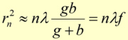
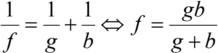
So the focal length of a Fresnel zone plate depends on the wavelength. In the last step the equation for the focal length f of a thin lens was used
Differentiating the approximated with respect to n gives the width of the nth ring

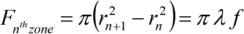
The surface of each zone is constant over the zone plate, when the wavelength and the focal length are fixed. This means that each zone contributes to the focus intensity with an equal amount of transmitted light
A grating mostly has more than one diffraction order. In a Fresnel zone plate this leads to more than one focus point (fig. 4, left). The negative diffraction orders even result in diverging beams, in other words: zone plates also behave like a dispersive lens with virtual focus points. When a zone plate is used as focusing lens, normally only the first diffraction order is used and all other orders have to be blocked by a suitable aperture (fig. 4, right).

Fig. 4: Diffraction orders of a circular grating (left); with order sorting aperture (right); first order rays marked red on mouse over 
Efficiency of Fresnel zone plates
Zone plates with absorbing gratings show about two times more absorption than zone plates using phase gratings. Additionally, light passing into unused orders is lost. The diffraction efficiency of a zone plate used in the mth diffraction order is defined as

with the incoming intensity I0 and the intensity in the mth diffraction order Im. Efficiency values of 5 to 30% for m = 1 are technically reached.
A zone plate with absorbing gratings reaches the theoretically possible diffraction efficiency only when the thickness of the absorbing structures is sufficient to absorb nearly 100% of the incoming light. When gold is used as absorber, and e. g. 90% absorption should be reached, the necessary thickness of the structures depends on the photon energy (fig. 5).
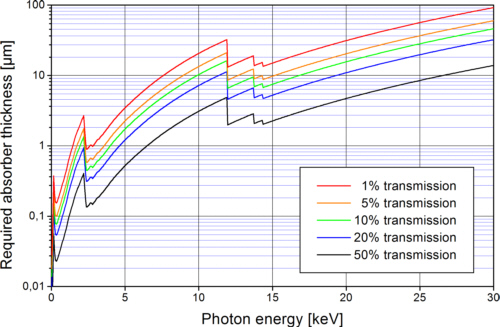
Fig. 5: Gold thickness required to absorb most of the incoming light in the zone plate rings
Spatial resolution of Fresnel zone plates and fabrication limitations
The spatial resolution  of a Fresnel zone plate depends, according to the Abbe theory, on the numerical entrance aperture NAE, ZP of the zone plate,
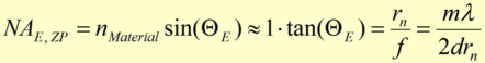
with the refractive index decrement nMaterial (= real part of the refractive index n*) of the medium between the object and the zone plate, the entrance acceptance angle  of the zone plate and the diffraction order m used. The following approximations were made: normally the entrance acceptance angle is small and the refractive index decrement nearly one.
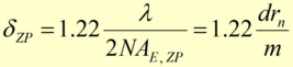
Based on the Rayleigh-criterion (resolution of two neighbour points resolved with a lens with the numerical aperture NA) the largest theoretical possible spatial resolution can be calculated for incoherent, monochromatic illumination to be
In the fabrication process of zone plates the gold absorbers are mostly produced by electroplating a micro structured substrate. The aspect ratio of these micro structures is defined as the ratio of structures height to the smallest lateral structure size. The highest aspect ratio realized in 2009 was in the region of about 120 using the LIGA-processLIGA-process. If the permitted transmission of the absorbing gold structures is relatively high, e.g. 50%, and the aspect ratio achieved in the process is e. g. 100, zone plate for 10 keV light with a minimum spot size of about 40 nm (fig. 6) are practicable. To achieve smaller spot sizes or the same spot size for larger photon energies either the required aspect ratio would have to be increased or the efficiency of the zone plate will decrease due to the increasing transmission of the absorber structures.
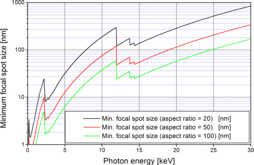
Fig. 6: Theoretically minimum achievable spot size when 50% transmission of the gold absorbers is tolerated
Reflexion Fresnel zone plates
XXX
Table 2 gives an overview over the principal parameters achieved with reflexion Fresnel zone plates in 2009.
| Parameter | symbol |
unit | Typical values |
|
| TER reflexion zone plate | Bragg-Fresnel-reflexion zone plate |
|||
| Object distance | g | mm | ∞-0.1 | ∞-3 |
| Image distance | b | mm | 0.1-∞ | 3-∞ |
| Photon energy range | EPhoton | keV | 0.01-1 | 1-100 |
| Angle of incidence | ΘZP | rad | 0.001-0.25 | 0.1-pi/2 |
| Minimal zone width | ΔZP | nm | 1000 | 200 |
| Horizontal Numerical Apertur | NAhorizontal | rad | 0.01-0.25 | 0.01-0.25 |
| Vertical Numerical Apertur | NAvertical | rad | 0.1-0.9 | 0.01-0.25 |
| Focal spot diameter | dU | µm | 1-10 | 0.1-10 |
| Intensity increase | K | 1 | 5-100 | 5-1000 |
Table 2: Typical parameters of reflexion X-ray Fresnel zone plates [VDI 2009d]
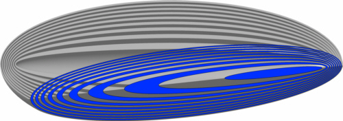
Fig. 7: Principle of a reflexion Fresnel zone plate
Condenser zone plates
Special zone plates are designed in order to be used as condensers illuminating the sample in full-field transmission x-ray microscopes. In this case a homogeneously and brightly illuminated square on the sample is required. The distance b from the condenser to the illuminated field, the size of the condenser and the size of the illuminated field Dzone have to be matched to the numerical aperture and the field of view of the microscope optics. A suitable condenser design (by PSI) is shown in fig. 8 [Jef 2008].
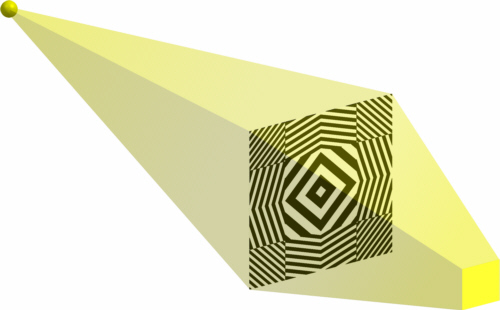
Fig. 8: Sketch of a condenser zone plate illuminating a square field
A square zone plate (e. g. 1 mm2) consists of many square gratings with the size of the required field of view (e. g. 20 x 20 fields, each 50 x 50 µm2). All grating grooves in one field are parallel and are oriented perpendicular to the line from the centre of the respective field to the centre of the zone plate (length of the line is Lzone). The grating constant gzone of each individual field, for a zone plate operating in first diffraction order, is chosen to be
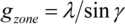
with (fig. 9)
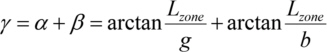
Under these conditions, the light passing any field will be diffracted towards the field of view on the sample.
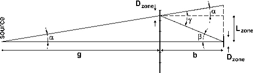
Fig. 9: Angles in the calculation of a condenser zone plate
| [Fre 1866] | A. J. Fresnel, "Calcul de l'intensité de la lumière au centre de l'ombre d'un ecran et d'une ouverture circulaires eclairés par un point radieux", in: Œuvres Complètes d'Augustin Fresnel, Imprimerie Impériale, Paris, 1866 |
| [Jef 2008] | K. Jefimovs, J. Vila-Comamala, M. Stampanoni, B. Kaulich, C. David, Beamshaping Condenser Lenses for Full-Field Transmission X-ray Microscopy, Journal of Synchrotron Radiation 15, p. 106-108, 2008 |
| [Kip 2001] | L. Kipp, M. Skibowski, R. L. Johnson, R. Berndt, R. Adelung, S. Harm, and R. Seemann, Sharper images by focusing soft X-rays with photon sieves, Nature, 414, 184, DOI: 10.1038/35102526, 2001 |
| [Sor 1875] | J. Soret, Über die durch Kreisgitter erzeugten Diffraktionsphänomene, Annalen der Physik und Chemie 156, p. 99-113, 1875 |
| [VDI 2009c] | VDI/VDE 5575 Blatt 5:2009-02 Röntgenoptische Systeme, Transmissionszonenplatten (X-ray optical systems; Transmission zone plates), Berlin, Beuth Verlag, 2009 |
| [VDI 2009d] | VDI/VDE 5575 Blatt 6:2009-03 Röntgenoptische Systeme, Reflexionszonenplatten (X-ray optical systems; Reflexion zone plates), Berlin, Beuth Verlag, 2009 |