")
")

Pin holes and coded masks are absorbing foils with one or more holes used instead of a lens for X-ray imaging purposes.
Pin holes
A pin hole camera consists of an absorbing foil with a small hole in the centre and a detector behind this wall (fig. 1). The rays coming from an object and passing the pin hole form an image of the object on the detector. The smaller the pin hole diameter, the sharper gets the image. This is limited, because diffraction effects increase with decreasing pin hole diameter. Most of the light coming from an object will not pass the pin hole, so the intensity in the detector plane is very low. The intensity in the detection plane decreases with increasing distance from the optical axis, because the pin hole appears elliptical seen from of axis points (fig. 1: darker corners in the image of the rectangular slit). This effect is called vignetting. When the thickness of the absorber foil can not be neglected compared to the diameter of the pin hole, the of-axis intensity decrease gets much worse.

Fig. 1: Sketch of a pin hole camera: test object (left), wall with pin hole (middle) and detection plane with simulated intensity distribution (right)
Coded masks
Imaging very hard X-rays in the MeV-photon energy range for example from astronomical sources is nearly impossible with mirror optics or other optics used for lower photon energies. In this case coded masks are used. A coded mask telescope works like a pin hole camera, but the small pin hole is replaced by a so called "coded mask" (fig. 2). This mask is a stronly absorbing plate made for example from tungsten with holes arranged in a special way. As the percentage of transparent areas in the mask is much larger than in a pin hole camera, the photon flux to the detector is much larger than in a pin hole camera. Each hole in the coded mask generates an image in the detector plane as in a pin hole camera. The large number of holes in the coded mask generates a lot of overlapping images. When the pattern of the mask is well designed, the real image can be calculated from the detector signals.
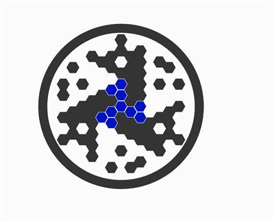
Fig. 2: Animated sketch of a coded mask telescope with housing and coded mask (dark gray) and 19 pixel detector (blue) as used in the spectrometer SPI (SPectrometer for INTEGRAL) aboard the INTEGRAL-mission